![]()
CIH Engine - Bosch FI Conversion
03.01.2002
![]()
Where do you start? What do you need?
- Intake manifold and all of it's
components:
Injectors; throttle body; throttle linkage and cable; fuel fittings, hoses and regulator - Air flow meter, air filter housing and flow meter air hoses
- Wiring harness with all relays (L - Dual Relay, LE – Main Relay)
- FI Controller (ECU, Computer)
- Distributor (’75 is vacuum retard only and limited to ~25° mechanical advance)
- Thermostat housing (water temp sensor, thermo-time sensor, auxiliary air valve mounted)
- Deceleration valve (L only)
- Fuel pump ('75 with special power connector plug) and filter
- 5/8” Heater Hose Nipple (near OP sender, instead of block coolant drain plug)
- Exhaust manifold
![]()
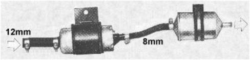
Fuel Line Routing: Yellow lines mark pressurized fuel lines, orange marks non-pressurized line back to tank. Hoses must be high quality and designed specifically for high pressure fuel injection (indicated on hose). A new line must be installed (at least 5/16” (~8mm) diameter) from pump at tank to engine room for pressurized fuel. Original nylon line (black or clear) may be used for flow back from engine compartment to tank and must be the same size as the pressure line so there's no restriction to fuel flow returning to the tank.
| 1.
2. 3. 4. 5. 6. 7. 8. 9. 10. 11. 12. 13. 14. 15. 16.
|
Air Filter Crankcase Vent Line Throttle Valve Body and Switch Air Flow Meter Intake Manifold Plenum Intake Air Hose - Air Flow Meter to Throttle Body Fuel Pressure Regulator Fuel Return Line Pressurized Fuel Line to Injectors (from EFP) Cold Start Injector Cold Start Injector Pressurized Fuel Line Vacuum Line to Fuel Pressure Regulator Auxiliary Air Valve Filtered Air Line (in front of Throttle Valve) Auxiliary Air Valve to Intake Manifold Line Auxiliary Air Valve (Cold Start) Deceleration Valve (used only on L type)
|
General Information :
Fuel pressure: 34-43 PSI (2.3-2.9 kg/cm²) Idle speed: 850-900 RPM (manual gearbox) CO in exhaust: max 1% Temp sensor resistance: 60-86ºF (15-30ºC): 1.45 - 3.3Kohm 176ºF (80ºC): 280 - 360ohm
![]()
Engine Compartment Wiring :

| |||
| 1.
2. 3. 4. 5. 6. 7. 8. 9. 10. 11. 12. 13. 14. 15. 16.
|
Cold Start injector Thermo-Time switch Injectors Throttle Valve switch Air Flow meter Auxiliary Air Valve (IAC Valve on LE models with integrated EAI ignition) Water Temperature sensor Distributor (including ignition controller on LE models with integrated EAI ignition) Ignition coil Battery FI wiring harness Vehicle wiring harness ECU - Electronic Control Unit (Computer) Connection to coil trigger (negative, green wire, connection terminal 1 in wiring diagrams) Common ground L - Dual Relay or LE - Main Relay
|
||
Additional Installation
requirements:
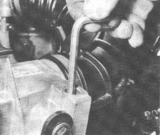
1.
As FI thermostat housings have no
provision for heater hose connection, remove engine drain plug under
exhaust manifold near the oil pressure sender and replace with hose
connector removed from original FI engine to connect second 5/8” (16mm)
hot water hose from block to heater control valve.
2.
Original fuel pump is no longer used
and may be removed. Using the original fuel pump spacer as template,
fabricate and install a thick 1/4" (~6mm) metal plate to cover original
pump hole in the timing chain cover.
3. Wiring diagram doesn't show clearly that the green wire from the control unit should be connected to the negative (points/trigger - connection terminal 1 in wiring diagrams) terminal of the ignition coil.
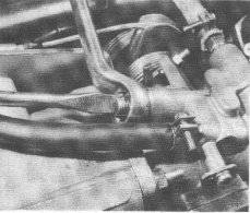
Adjustments:
After installation, everything should now work. However, if idling is poor, mixture and idle speed can be adjusted. Check all rubber airway and vacuum hoses and connections for leaks before making any adjustments.
|
Adjust idle mixture (clockwise is richer) with a screwdriver on L or a hex key on LE (shown)
|
Adjust idle speed (clockwise is slower) with a 15mm box end wrench and screwdriver
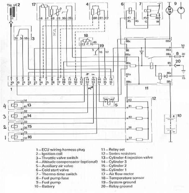
Pin Outs - Dual Relay:
1. ECU plug
strip
3. Temperature
sensor
4. Ground
5. Auxiliary Air
valve
12. Control
relay
6. Throttle valve
switch
7. Air Flow
meter
14. Fuel
pump
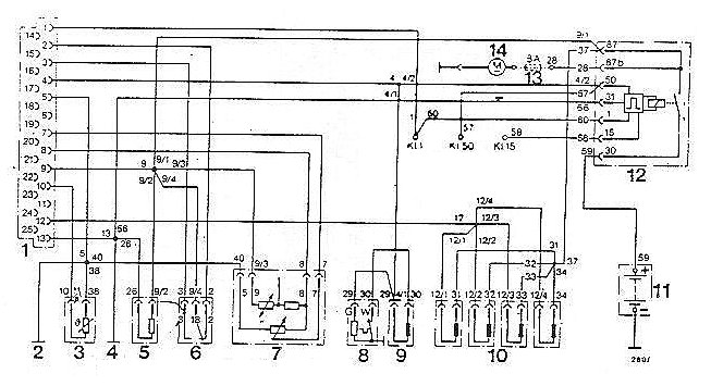
Pin Outs - Main Control Relay :

Pin Outs - Main Control Relay :